Building the L-Star Plus (Rev. 5)
So you bought the L-Star Plus kit, and you’re ready to put it together. You’ve come to the right place!
Before you begin
If you’ve done plenty of soldering before, this article probably won’t tell you many of things you don’t already know. Nevertheless, you may want to glance over it to catch some helpful hints.
On the other hand, if you’ve never soldered anything before, I recommend that you don’t make this your first soldering project. I can’t stop you of course, and L-Star is really not difficult to put together, but it will be a lot more fun to do if you already know how to avoid pitfalls such as:
- Using the wrong solder iron or the wrong tip or the wrong solder tin
- Overheating electronic parts as well as body parts
- Causing cold solder joints
- Causing short circuits
- etc.
I suggest you google for “Learn how to solder” and learn some of the basics, even if you’re only going to watch some pictures or online movies that show how to do it right. You can also get low-cost kits from many sources that will teach you all the details while you do it.
I’ll try to keep the instructions easy enough for a beginner to understand, but teaching you how to solder and how to recognize the components is outside the scope of this article. I hope you don’t mind.
NOTE: click on any of the photos to see an enlarged version.
Let’s get started
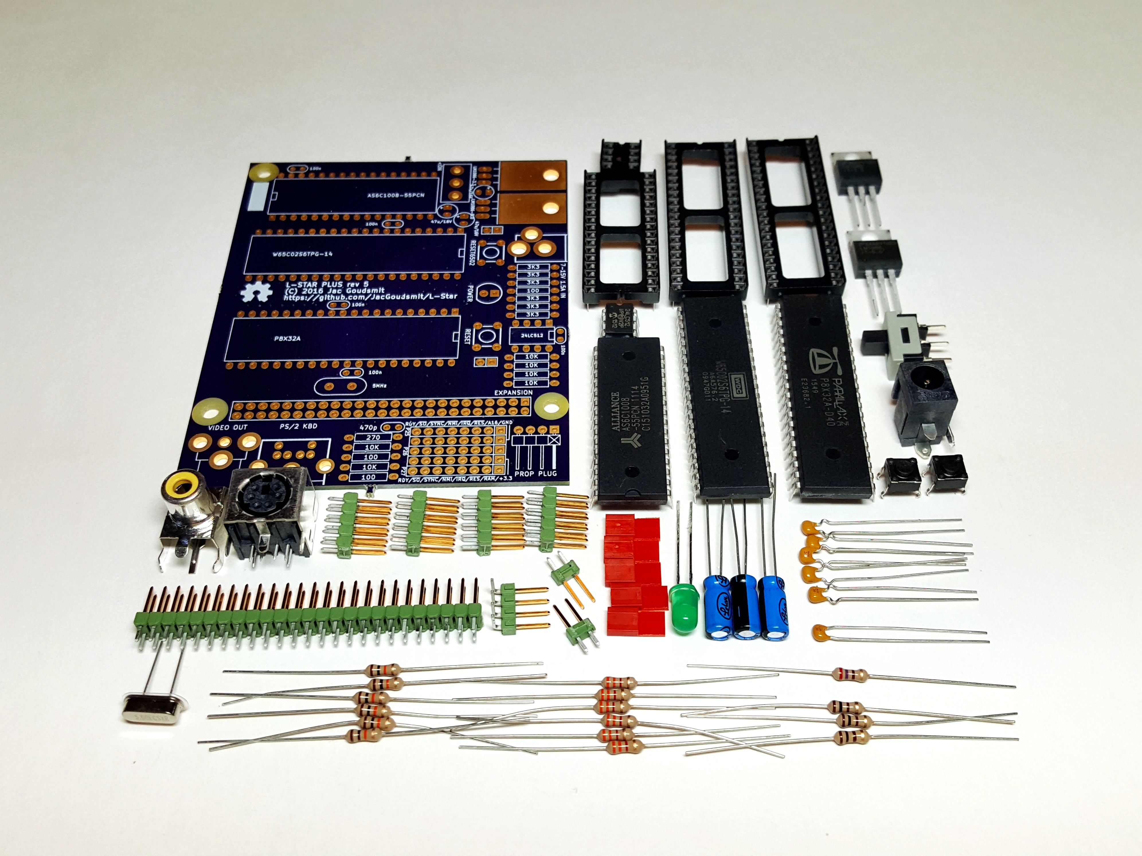
You should have received the following components. Please contact me if anything is missing:
- 1x Printed Circuit Board
- 1x SRAM chip: Alliance AS6C1008-55PCN (128KB), with 32 pin socket
- 1x 65C02: Western Design Center W65C02S6TPG-14, with 40 pin socket
- 1x Propeller: Parallax P8X32A-D40, with 40 pin socket
- 1x EEPROM: Microchip 24LC512-I/P (64KB), with 8-pin socket
- 1x LDO Voltage Regulator 5V/1.5A: Texas Instruments LM1086-5V
- 1x LDO Voltage Regulator 3.3V/1.5A: Texas Instruments LM1086-3.3V
- 1x Crystal 5MHz with insulator
- 1x Green LED
- 3x Electrolytic Capacitor 47uF/16V
- 5x MLCC Capacitor 100nF
- 1x MLCC Capacitor 470pF
- 3x Resistor 100 Ohm (brown, black, brown, gold)
- 1x Resistor 270 Ohm (red, violet, brown, gold)
- 6x Resistor 3300 Ohm (orange, orange, red, gold)
- 6x Resistor 10k Ohm (brown, black, orange, gold)
- 1x RCA socket (monochrome video output)
- 1x Mini-din 6 socket (PS/2 keyboard)
- 1x Power socket (barrel connector 2.5mm)
- 1x Power switch
- 2x Tactile switch (push buttons)
- 1x Header 1×4 pins, right angle (Propeller plug)
- 1x Header 2×25 pins (Expansion port)
- 4x Header 2×5 pins (Jumpers)
- 2x Header 1×2 pins (Reset jumpers)
- 5x Shunt (for jumpers)
When you get the kit, the IC’s are mounted on a piece of conductive foam to protect them from electrostatic discharge (ESD) during transport. Leave the chips on the conductive foam until you’re ready to mount them on the board. The other parts are not static sensitive, but I may use the foam to protect other parts from from getting damaged, or causing damage to other parts.
Resistors
The first resistor you’re going to solder onto the board is the 270 Ohm resistor. The rings are colored red, violet, brown, gold. It doesn’t matter which way you solder it but I like to be consistent and solder all resistors in the same direction just to make it look good.
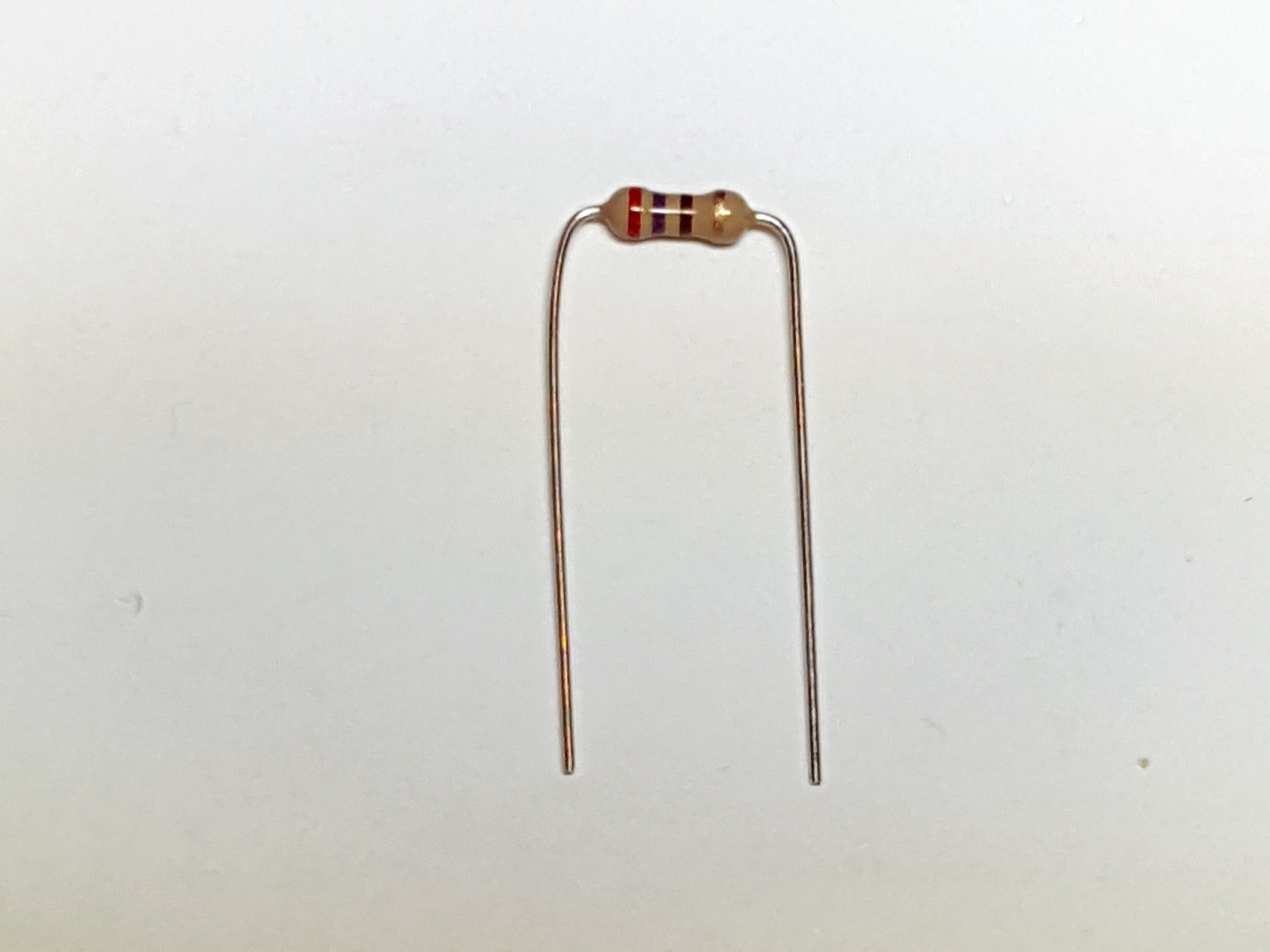
Bend the leads as shown in the picture above, and insert the wires into the board on the top side, where it says “270”. While you hold the resistor against the board, bend the wires on the other side so they’re at 45 degree angles.

Then, turn the board over and solder the wires.

Then use side cutters to cut the wires as close to the board as you can.
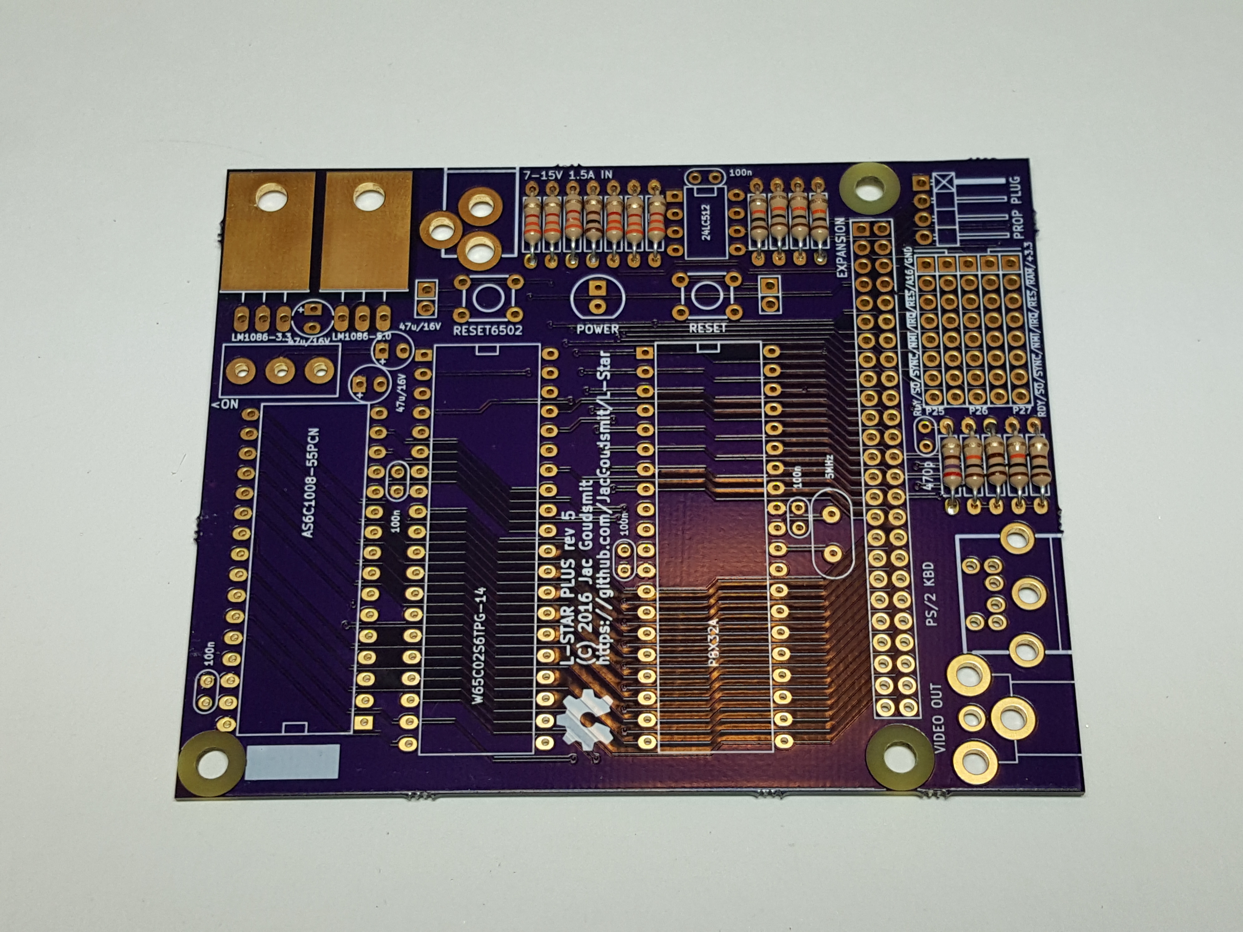
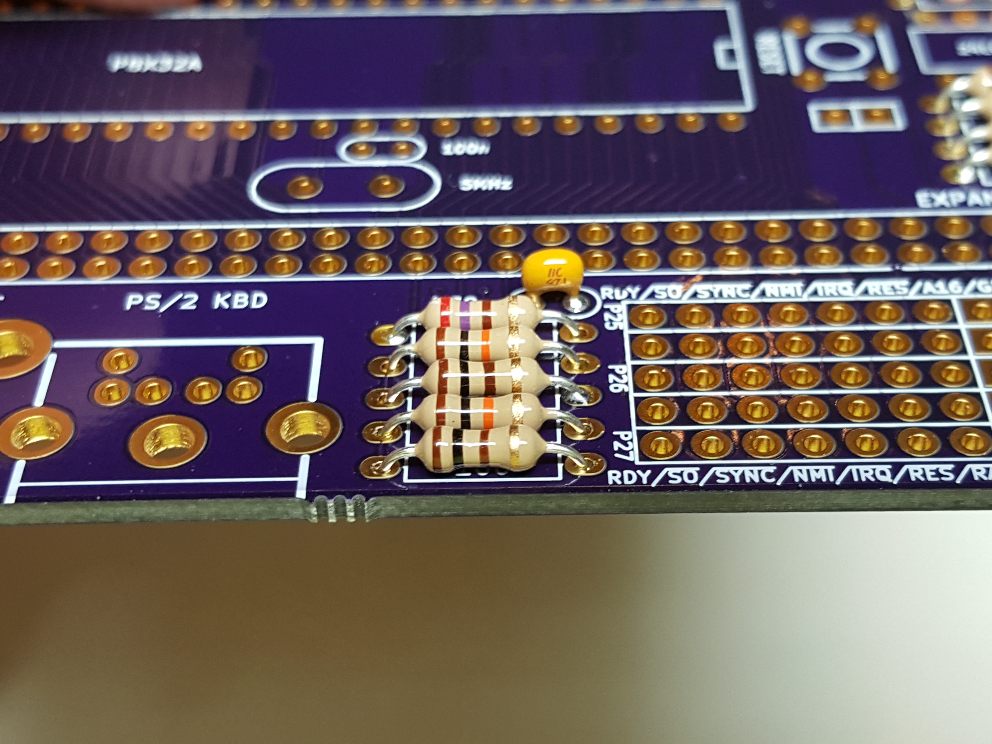
Repeat this for the other resistors. The 270 Ohm resistor was the only one of its kind, but there are six resistors of 10K (brown, black, orange, gold):
Three resistors of 100 Ohms (brown, black, brown, gold)
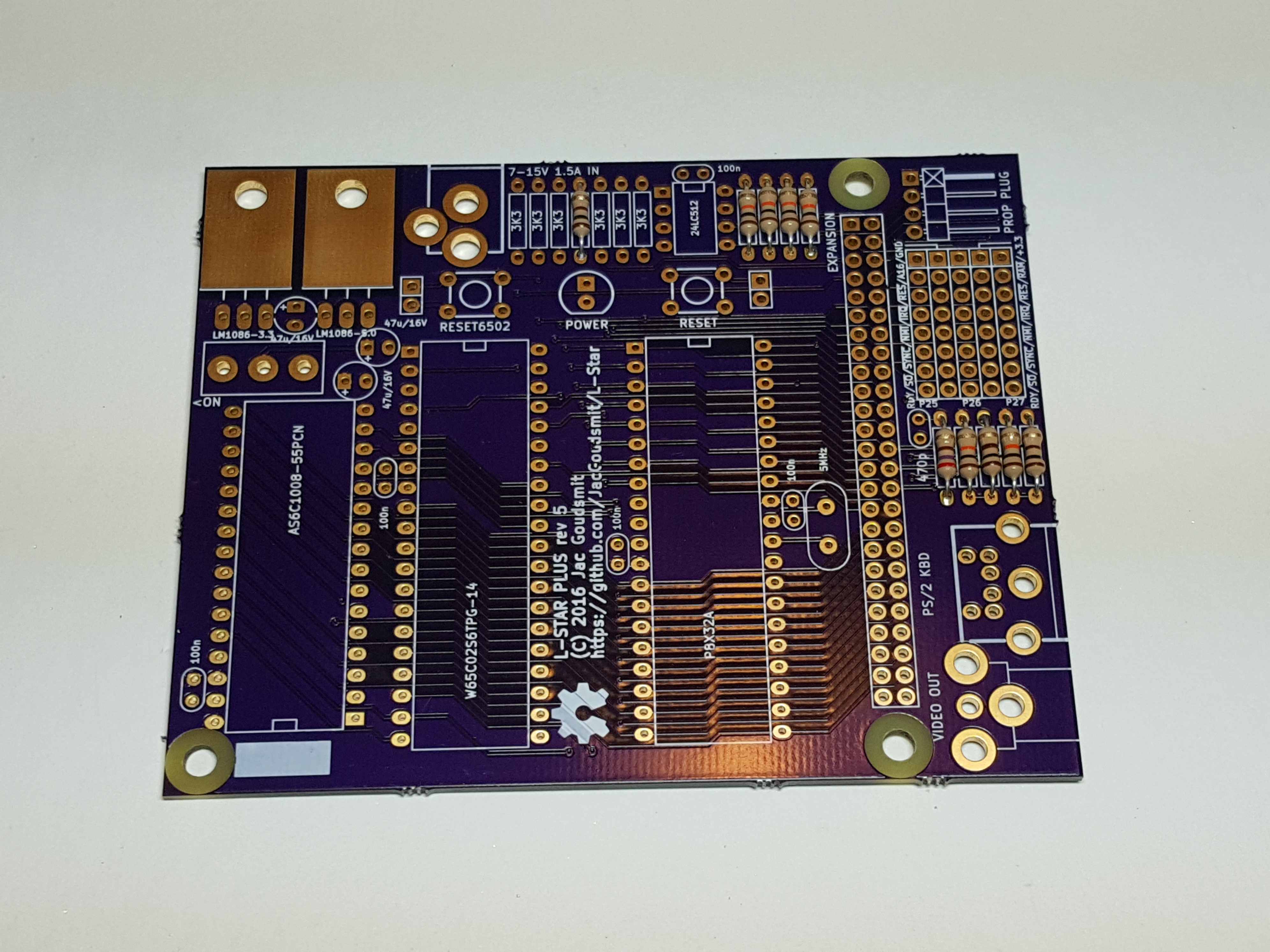
Six resistors of 3300 Ohms (3K3) (orange, orange, red, gold)
Capacitors
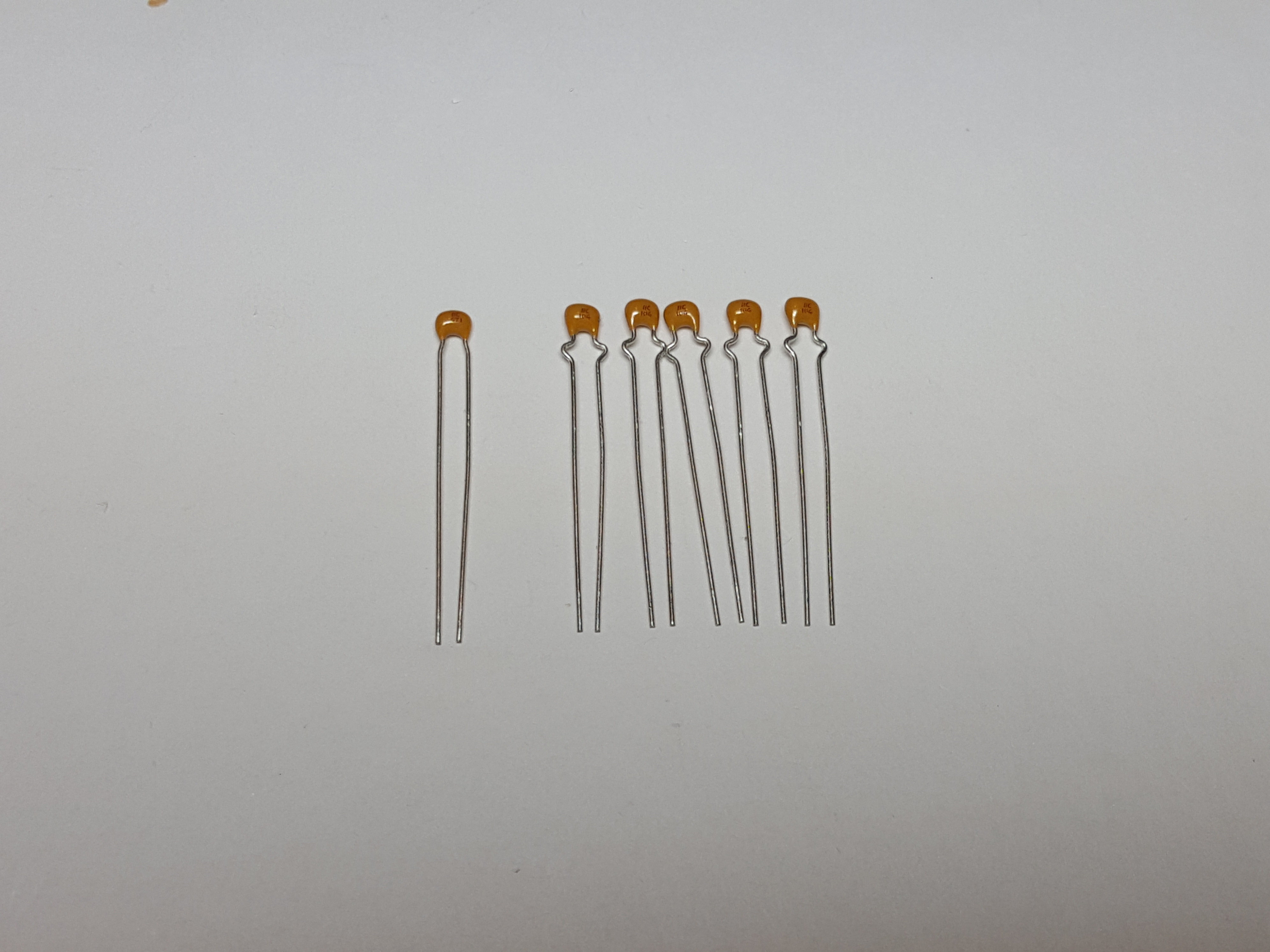
Start by soldering the 470 pF MLCC capacitor near the 270 Ohm resistor. The value on the MLCC capacitors may be hard to read and the capacitors look very similar, but the 470 pF capacitor has straight leads whereas the other MLCC capacitors have a little “curl” in them, as shown in the following picture:
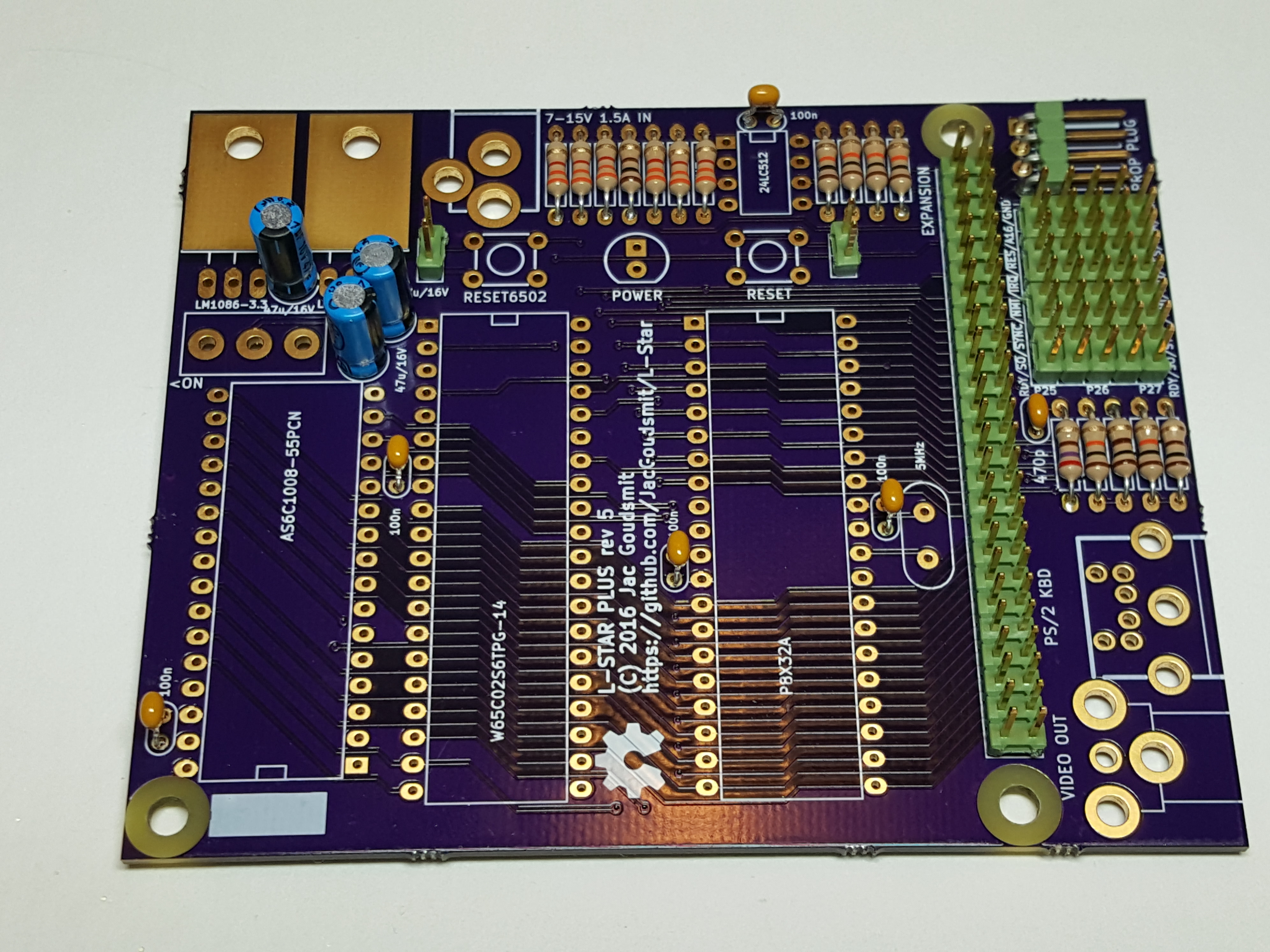
The next photo shows where that single 470pF capacitor goes:
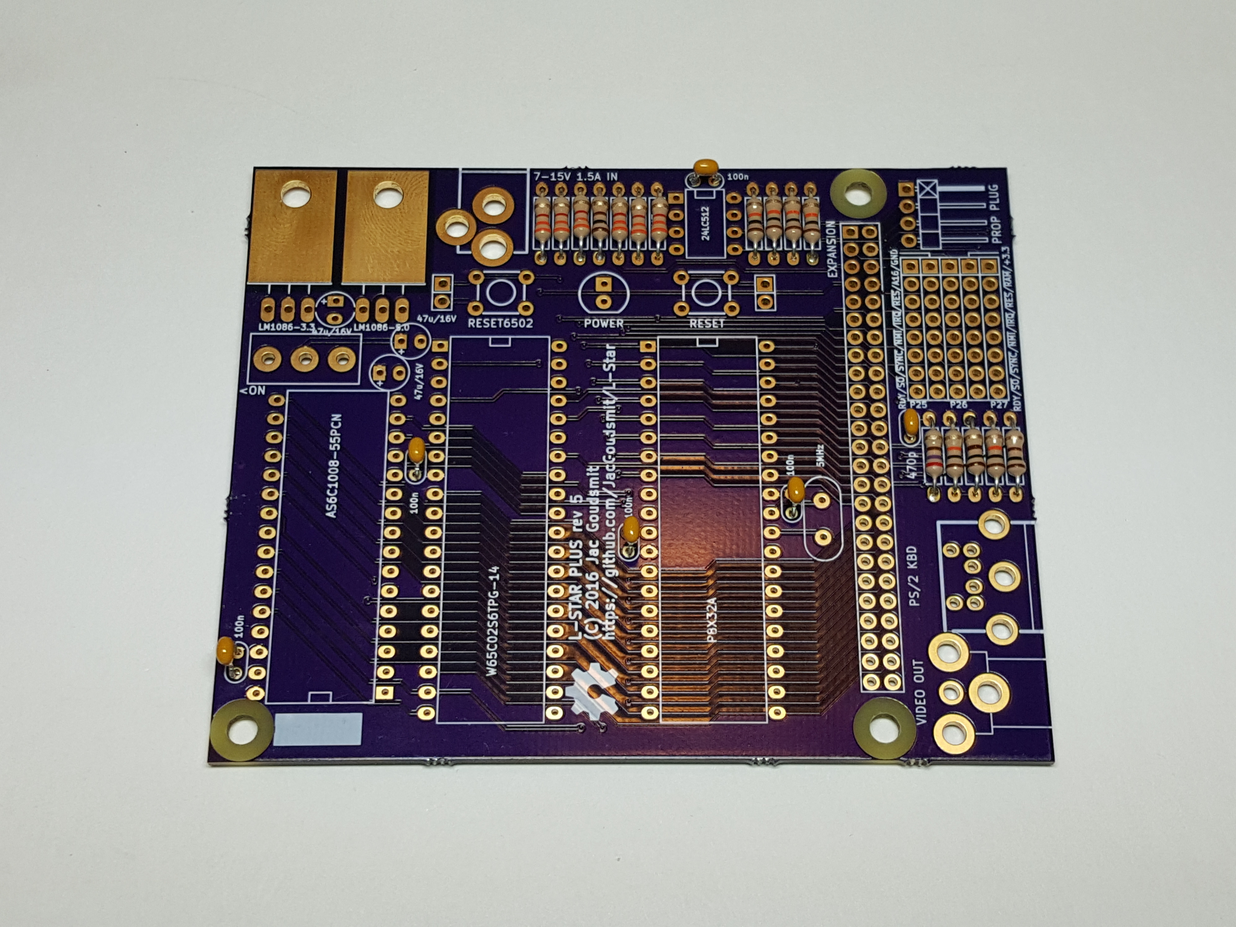
The other five MLCC capacitors are all 100 nF, and this picture shows where they go (once again: click on any picture to see an enlarged version):
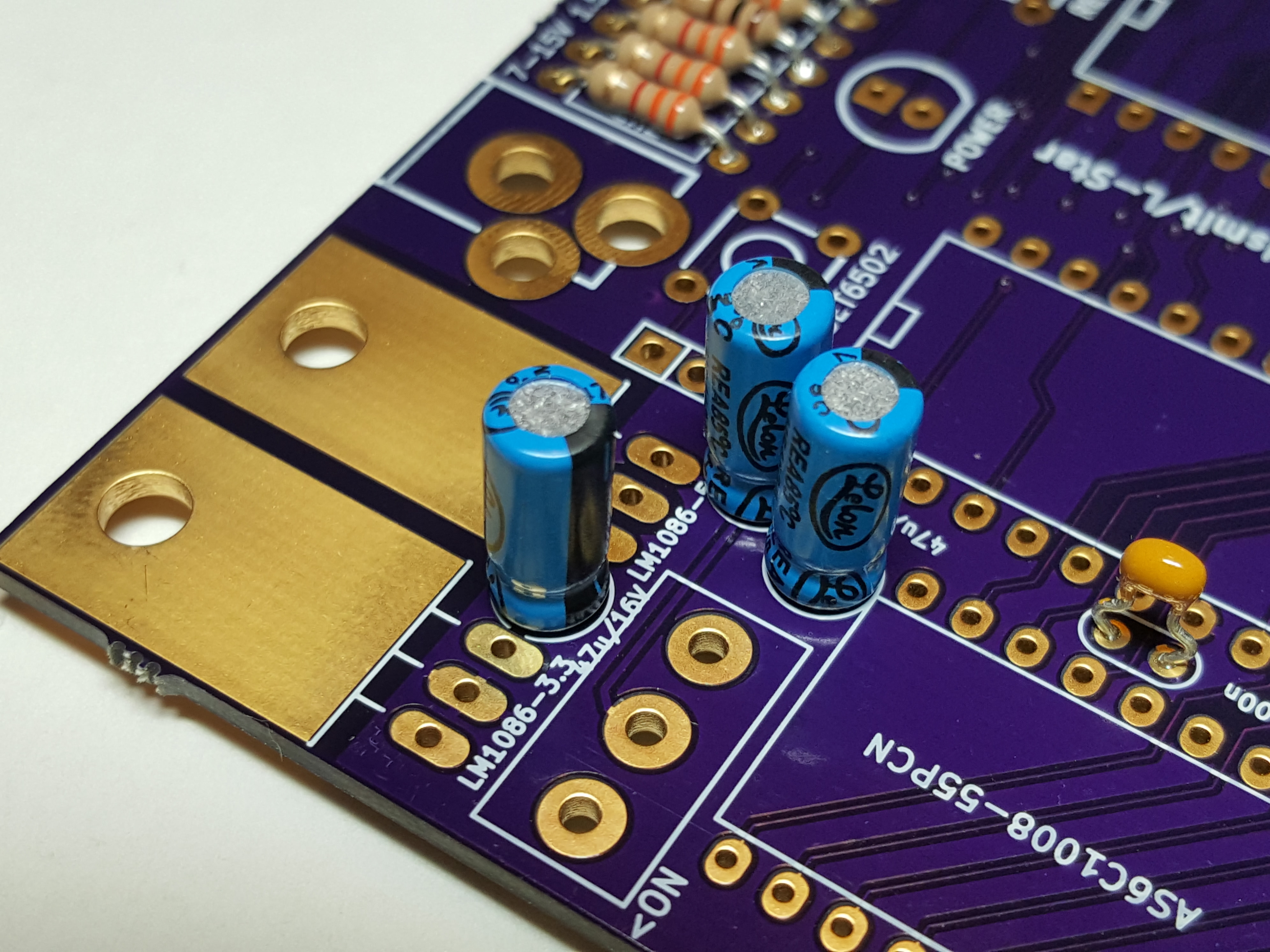
 Finally, solder the electrolytic capacitors. These are polarized, make sure you solder the ‘+’ lead to the square pad, and the ‘-‘ lead (usually shorter, and indicated by a black band) to the round pad.
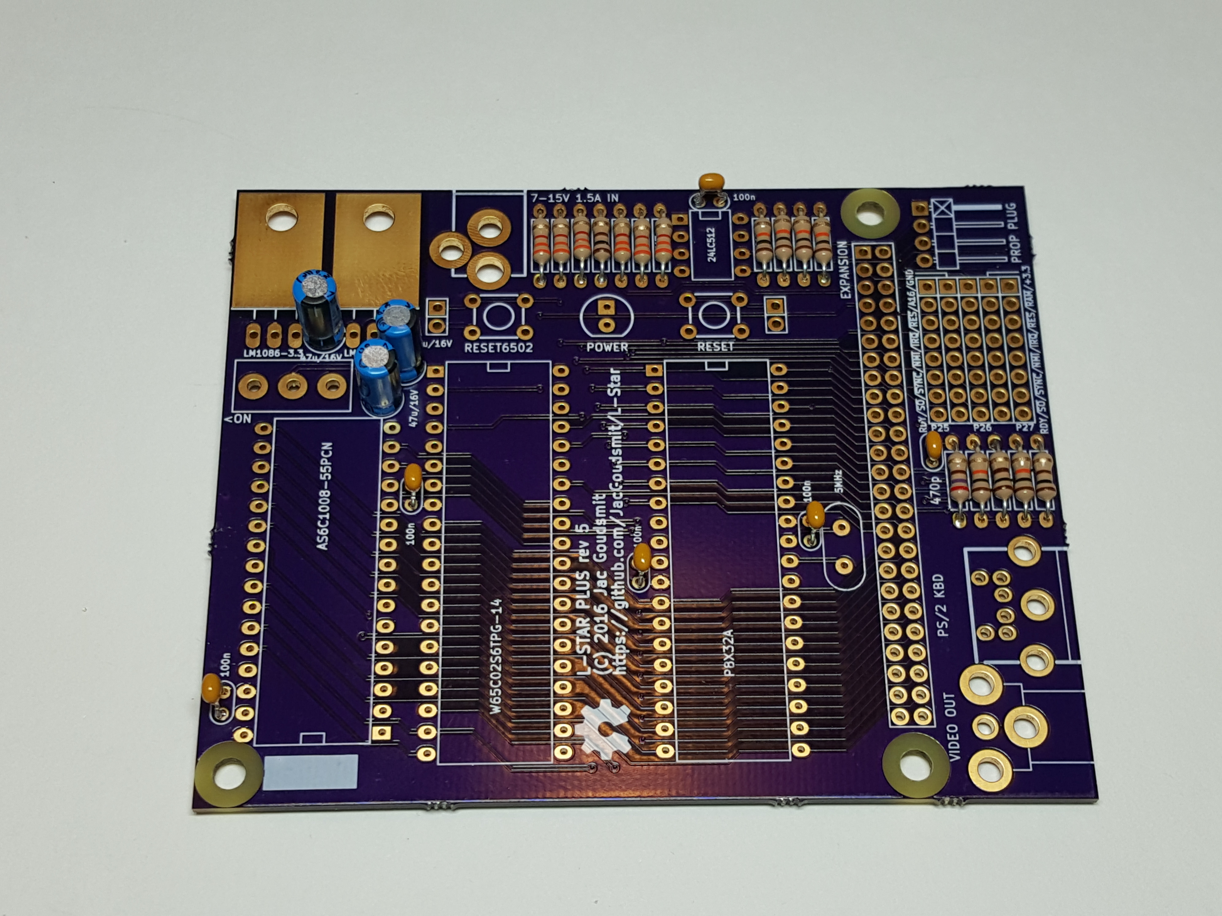 Here’s a detail picture that shows you which way the electrolytic caps should be soldered. Pay attention to the black band (or ‘-‘ signs) on the packaging.
Headers
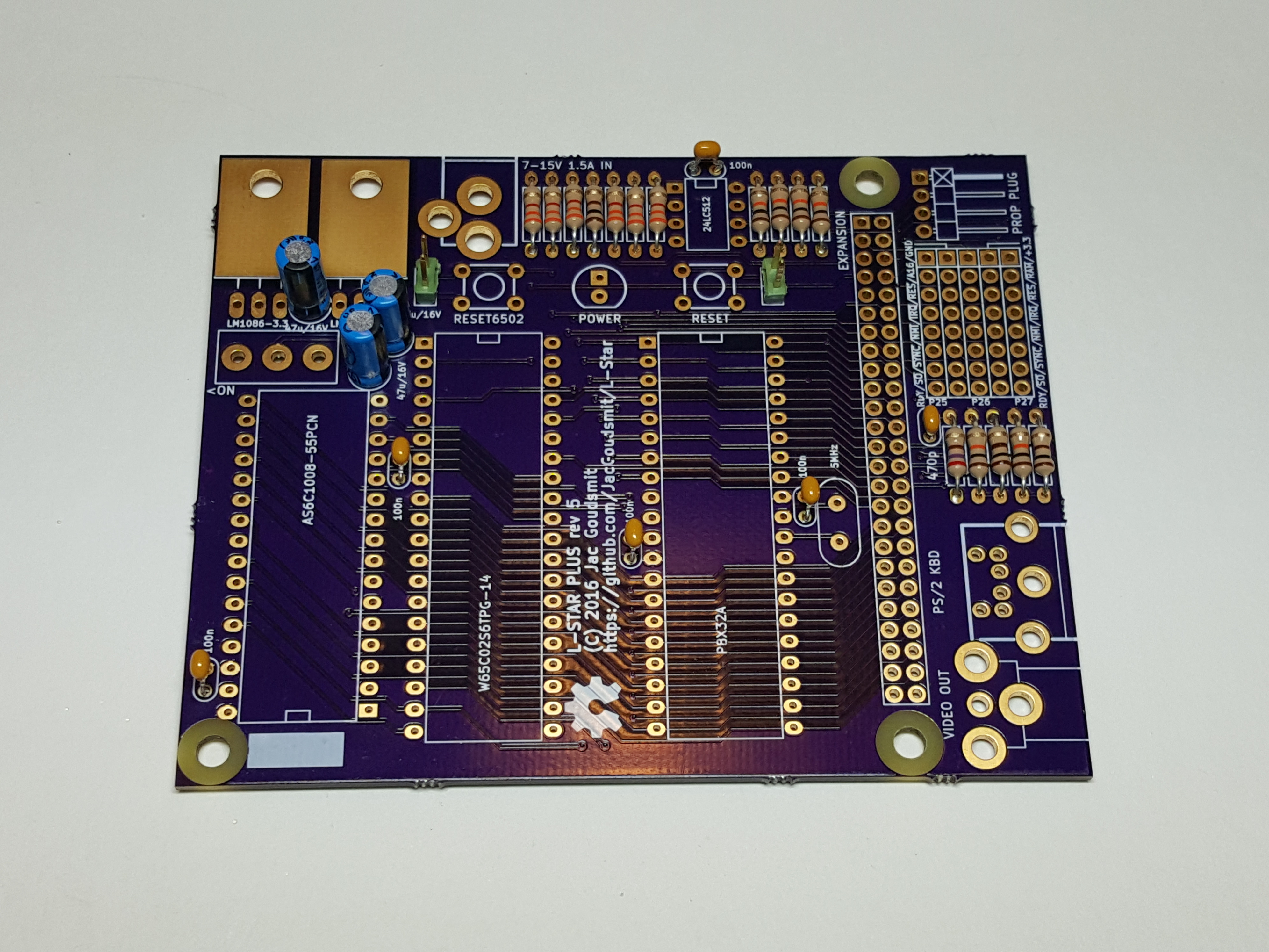
The project has two push buttons that we’re going to solder later, to reset the 65C02 and the Propeller, but in case you’re going to put the project into an enclosure, you’re going to want to put some push buttons with normally-open momentary switches in that enclosure. They can be attached to the two-pin headers that are next to where the push buttons are going to be on the PCB. The kit includes a couple of 2-pin headers in case you want to use connectors, but you don’t have to solder these headers. This is what it looks like if you do:
 One thing you will definitely need is the header for the Propeller Plug. This is used to connect the L-Star project to a PC. The Propeller plug contains an FTDI chip (which are not available in through-hole), and a small resistor-capacitor-transistor circuit that pulses the reset line of the Propeller. You will need a Prop Plug to use the L-Star project.
The Prop Plug header is at a right-angle, and the short leads of the header (the ones that have the right angle) are the ones that go through the circuit board. The long (straight) side of the leads will point towards the edge of the circuit board.
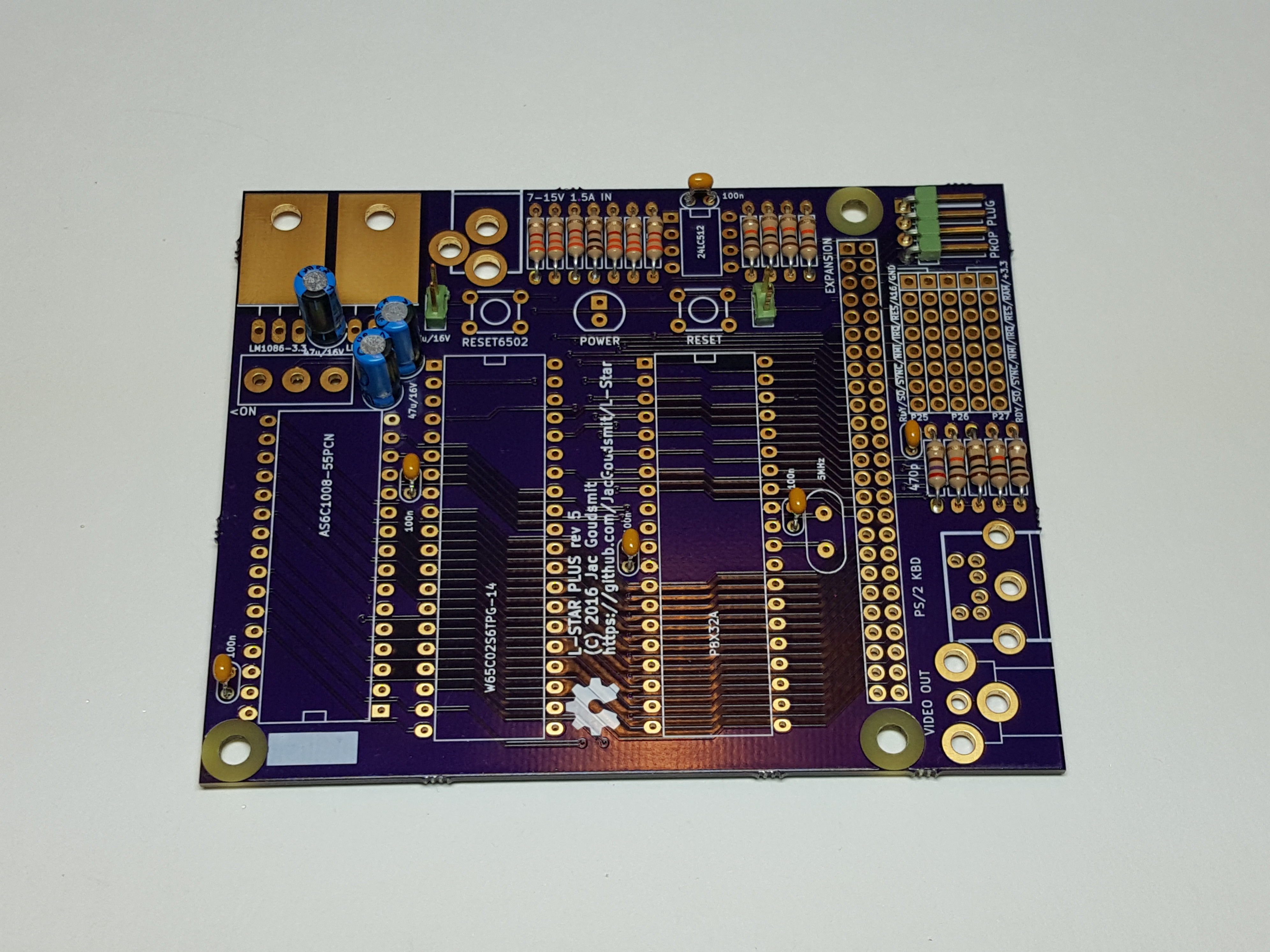 Next, solder the pins of the jumper block. You should have four headers of 5×2 pins each. The headers for the jumper block are mounted perpendicular to the lines of the drawing on the silk screen: In the previous picture you could see the lines in the jumper block go from front to back, but in the picture below you can see that the actual headers are mounted from left to right. The reason I did it this way is that it’s much easier to solder and align two-row headers than single-row headers. And here’s a little secret: all the headers except the one for the Prop Plug start out as one long dual row header which I cut down to the right size for you. This reduces the cost of the kit a little.
Make sure your headers are all the way down on the board and line up perfectly; you may want to start by soldering just one pin at one end of the header, then inspect your work on both sides (desolder the pin and correct the alignment if necessary) before you solder all the pins to the board.
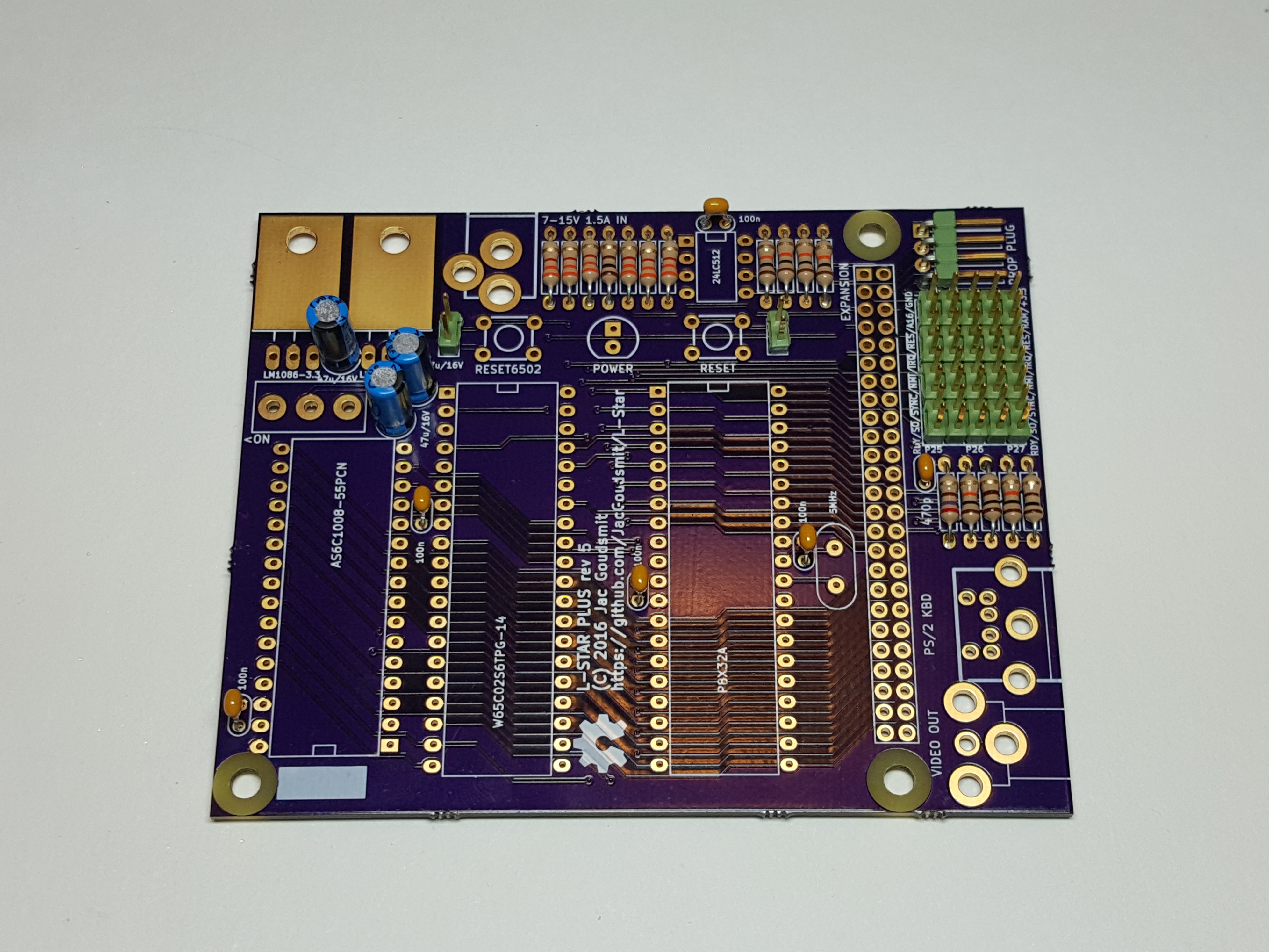 The expansion header is the last header to solder, and it’s 50 pins. It’s not needed for all projects, but you may want to solder it anyway in case you want to buy an expansion board later, or design your own. Again, I recommend you start by soldering a single pin at the end of the connector, then inspect your work and make sure the entire header is perpendicular to the board (make corrections if necessary by desoldering the one pin), and when you’re absolutely satisfied that the header is in the right place, solder all the other pins.
IC Sockets
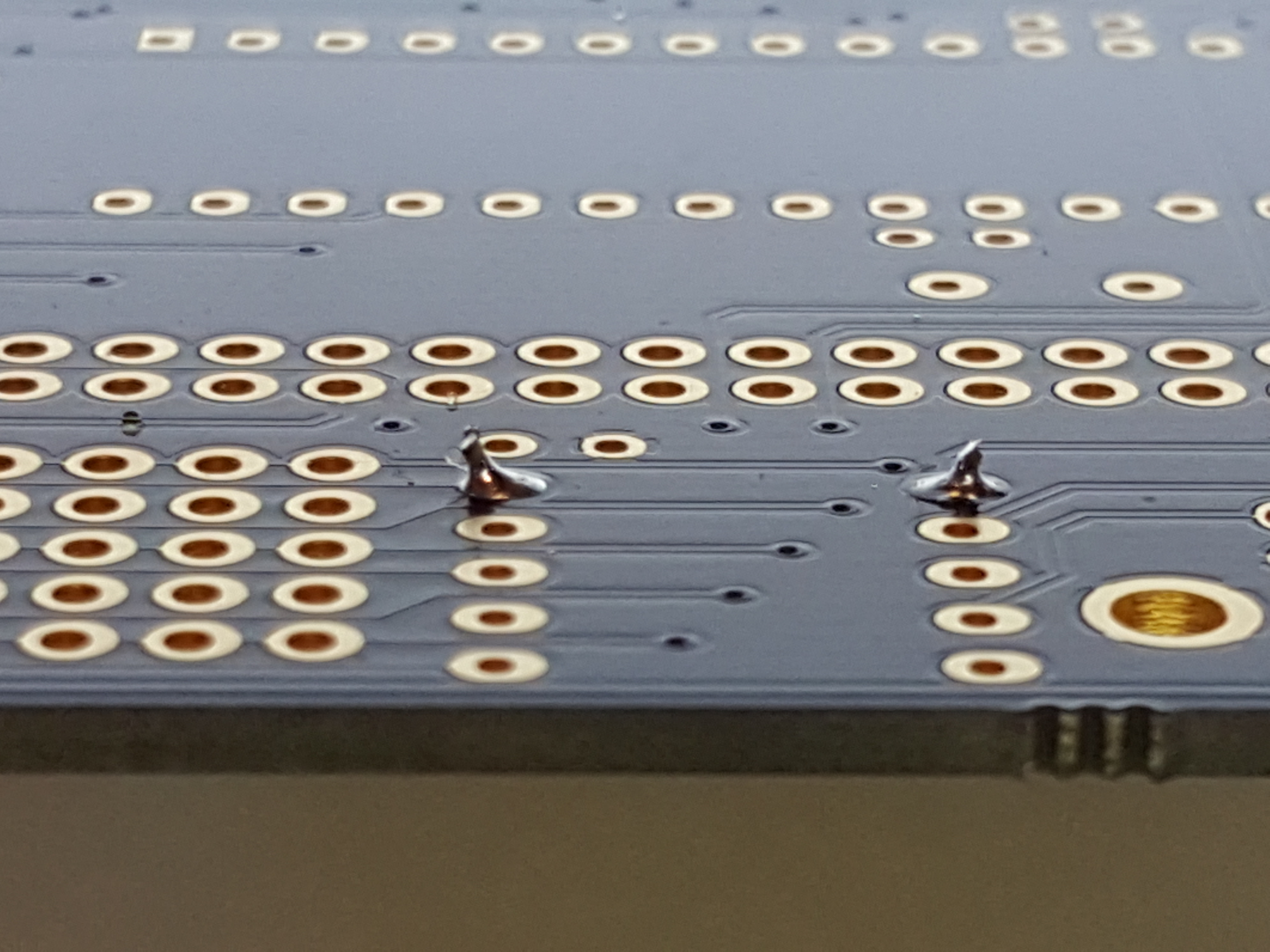
Soldering the sockets is tedious, but it needs to be done. Just like with the other big parts, I recommend starting with soldering a single pin on a corner, then verifying that the entire socket is completely in the right place, then soldering the other pins.
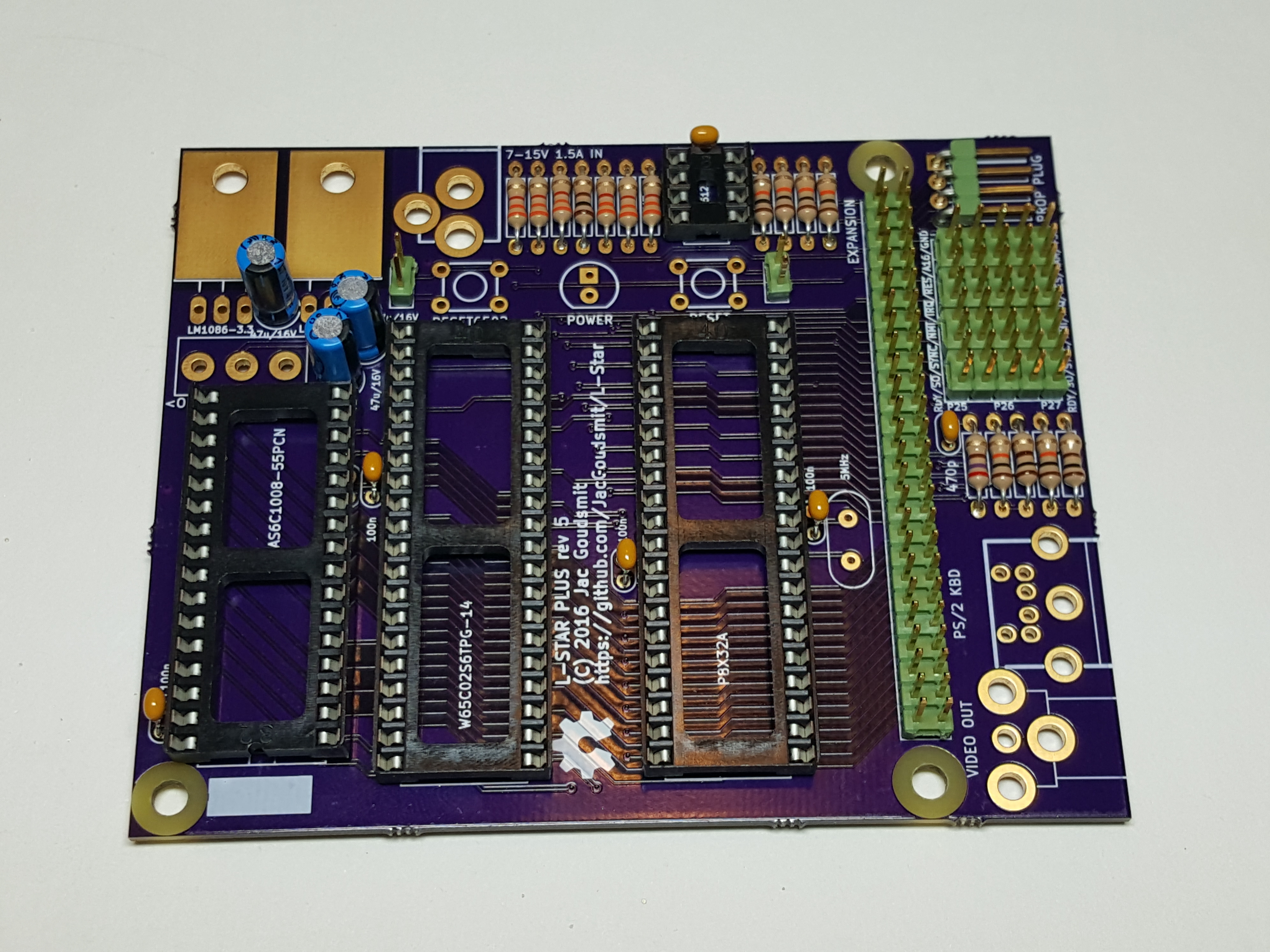
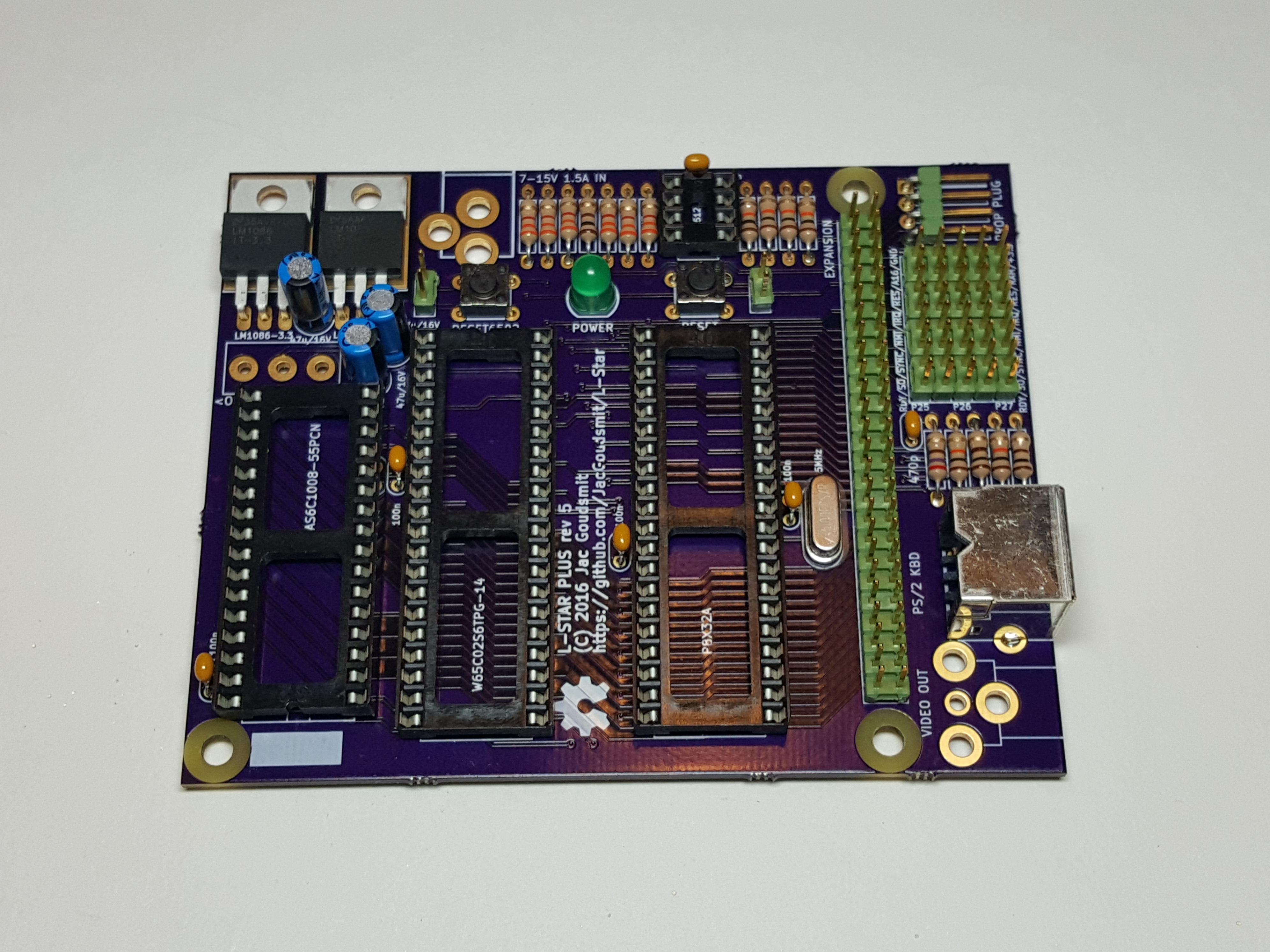
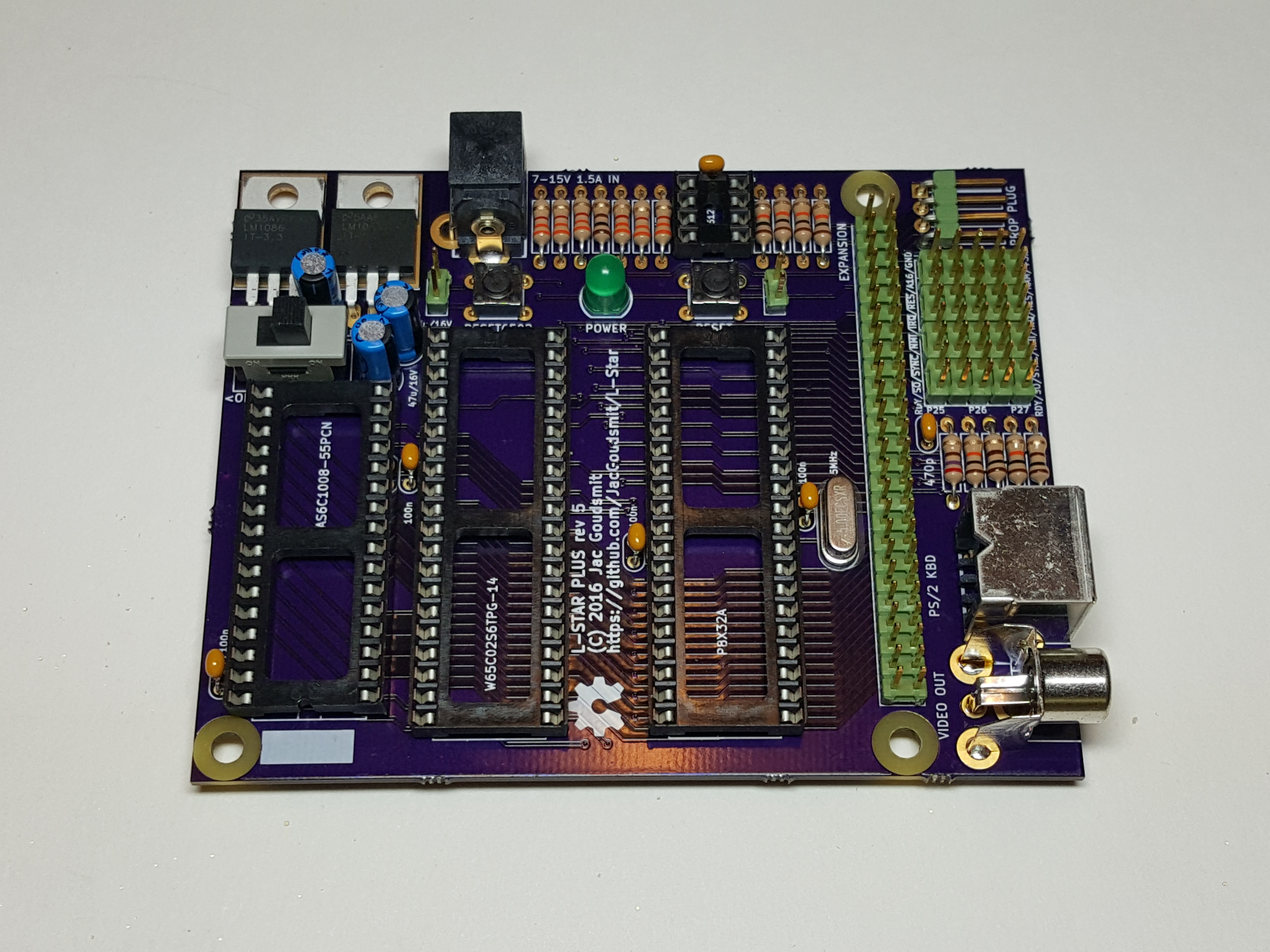
Pay close attention to the orientation of each socket! The SRAM chip on the left of the pictures (the one with 32 pins) is the only one that has its notch pointed to the bottom of the board, all the other ICs point the other way, with their notches towards the top of the board. It’s very important to get this right, so you don’t make mistakes when you insert the IC’s later on.
Just a Few More Parts…
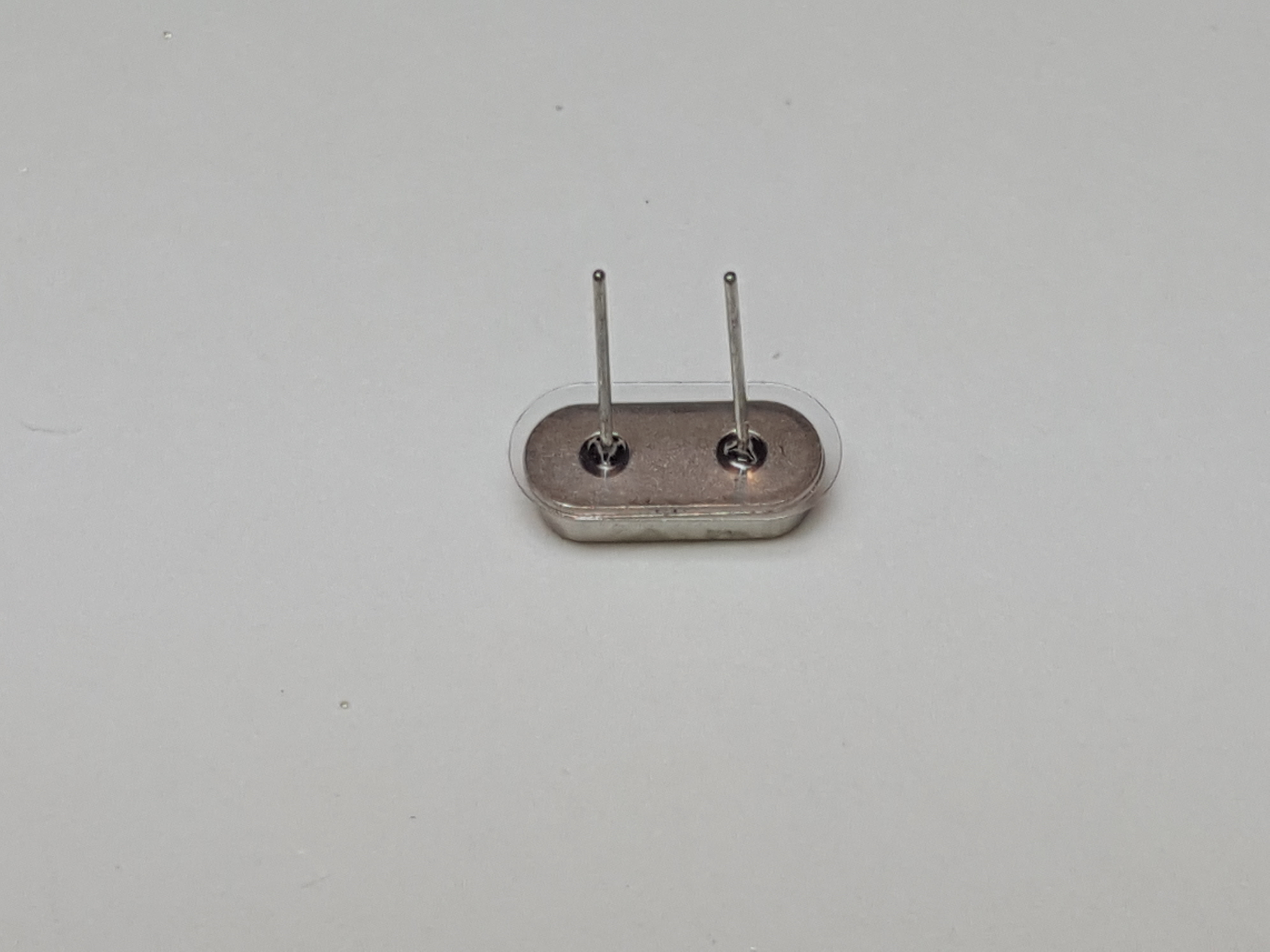
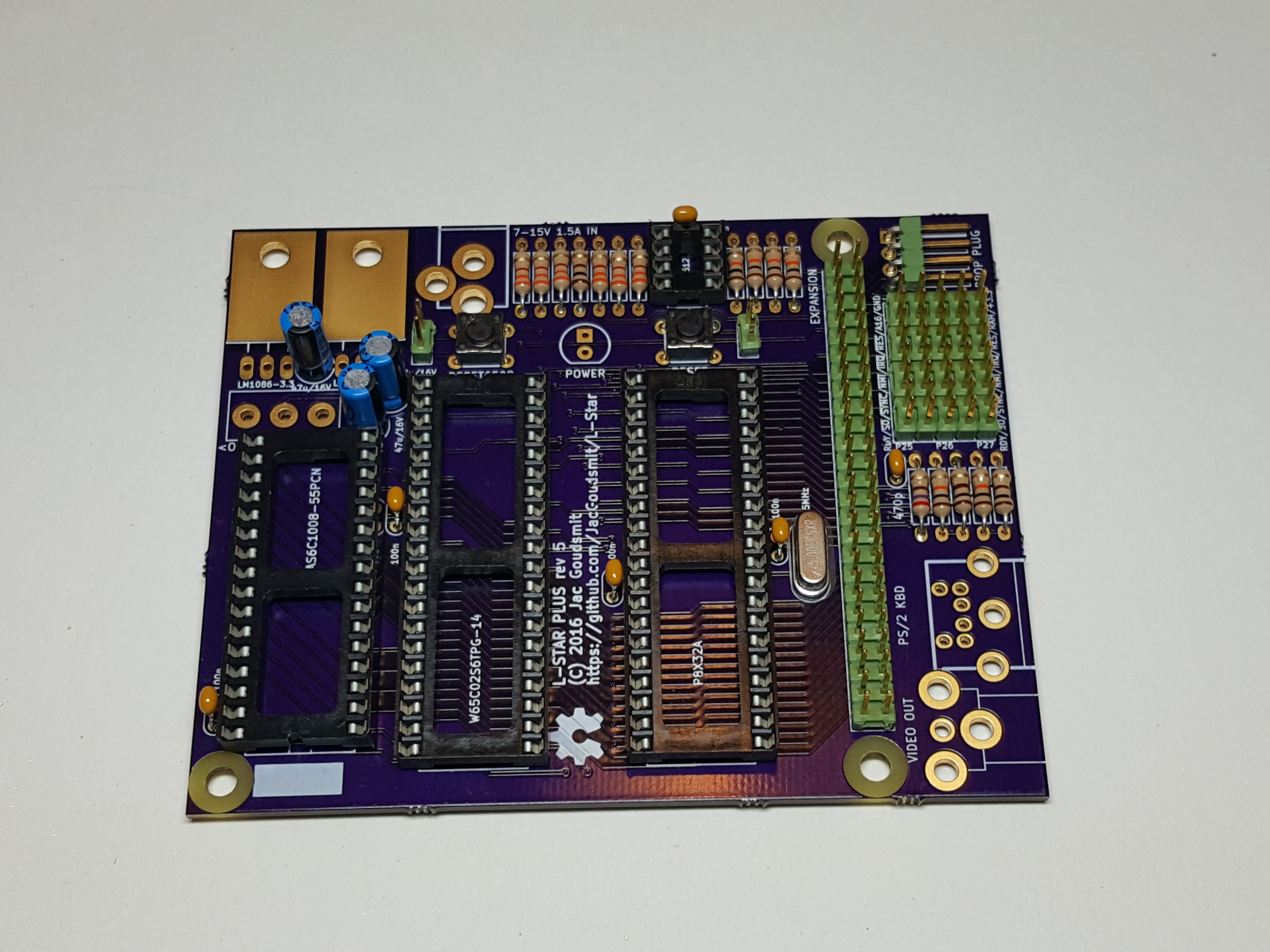
The crystal should have a transparent plastic insulator on it, that keeps it from causing a short-circuit. Without it, the metal housing of the crystal might touch the soldering pads, which would make the circuit stop working. Do not remove the insulator. If the insulator gets lost, replace it with a piece of thin cardboard, thick paper, or plastic.
The two tactile switches should be easy: they’re even designed in such a way that their legs “grab on” to the circuit board when you put them in. The ones you got in your kit may look a bit different from the picture:
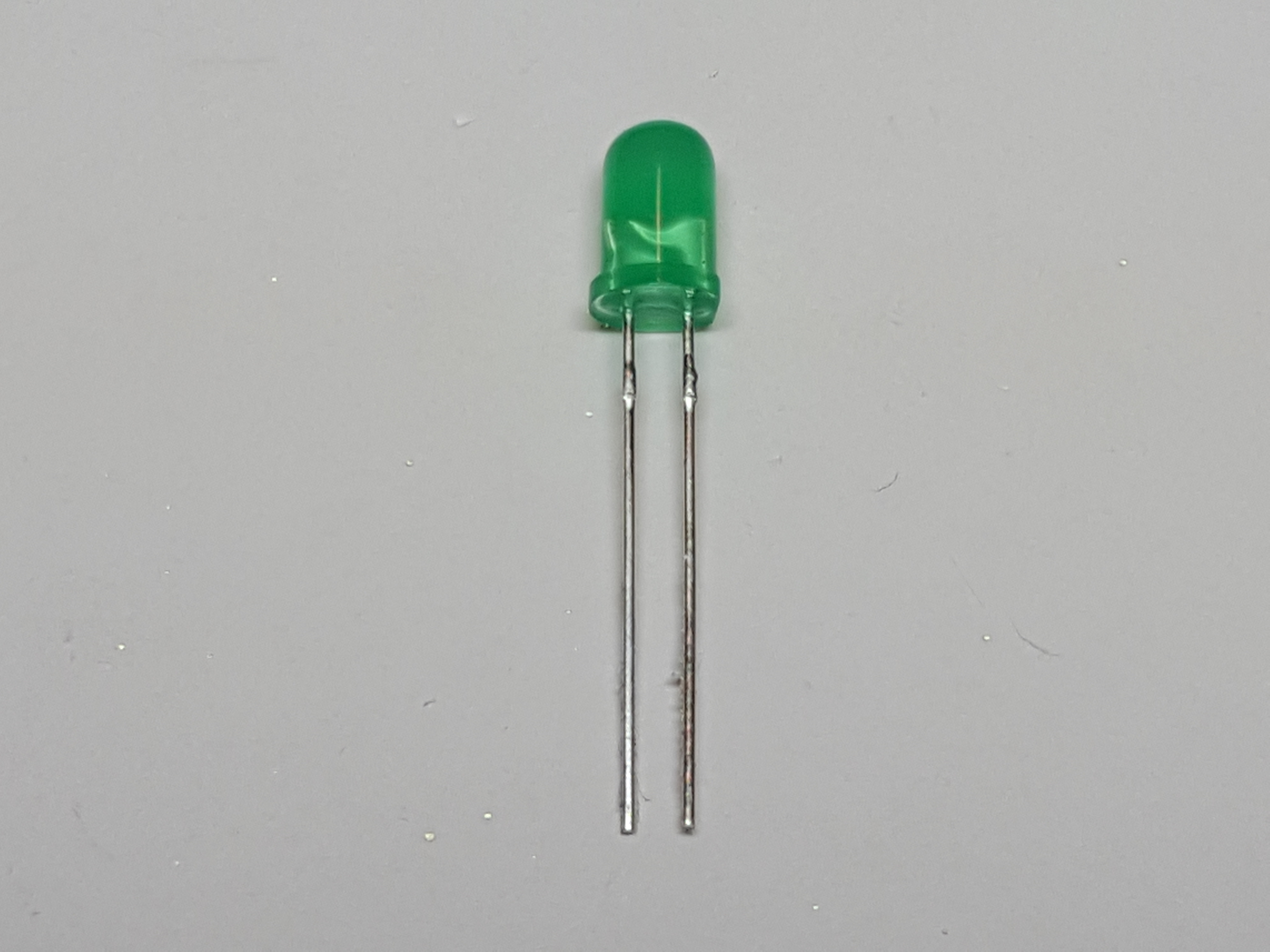
 Next, let’s do the power LED. It will only work if you mount it the right way, so pay attention to the orientation. The anode goes towards the top (in the hole with the rectangular pad), and the cathode goes towards the bottom (round pad). The anode of the LED has a longer wire, and the body of the LED is flattened on the cathode side. In the picture below, the anode is on the left and the cathode is on the right. If you look inside the translucent housing, you’ll also see that the cathode is always a little bigger: the little crystal that lights up inside the LED is mounted on top of the cathode.
Voltage Regulators
There are two voltage regulators on the board: one that generates 5 Volts, and one that generates 3.3 Volts. The 3.3V regulator goes on the left, and the 5 V regulator goes on the right. Don’t mix them up! The voltage is laser-etched in the regulator as part of the type, and can be hard to read.
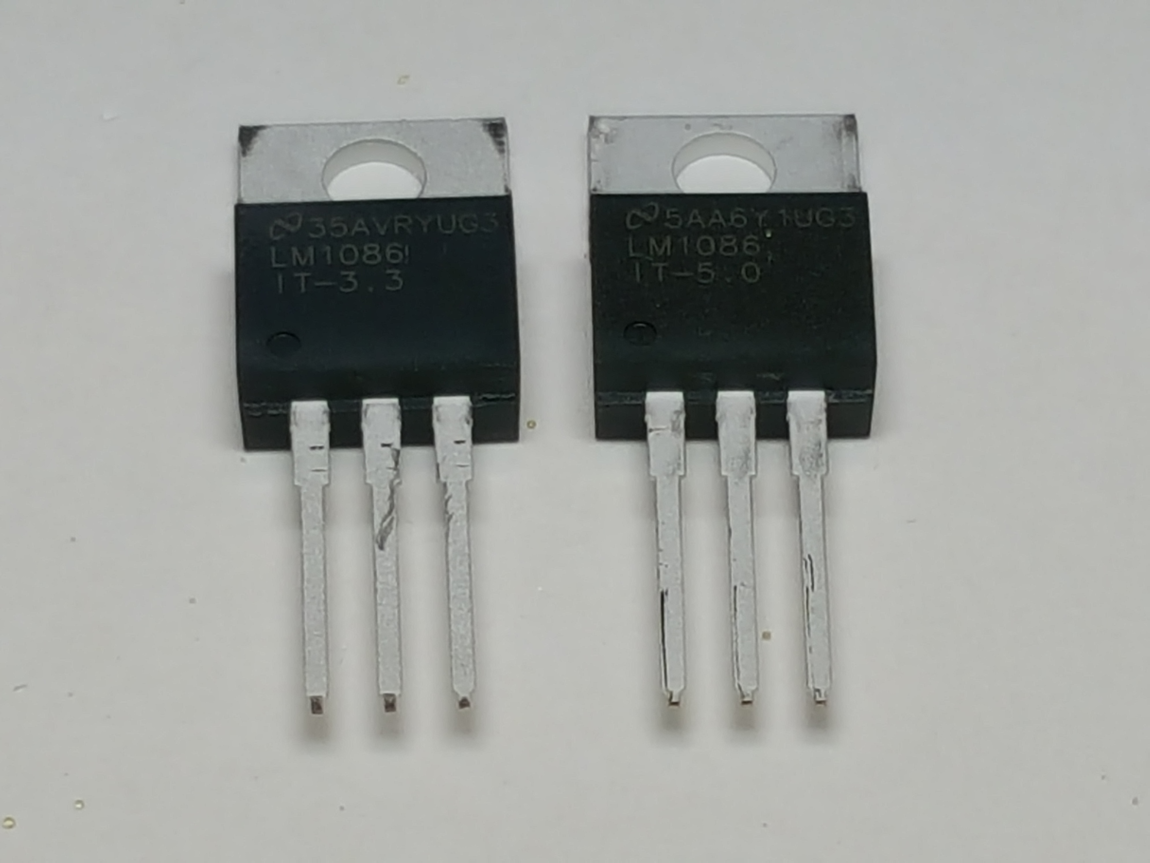
If you look closely at the leads of each regulator, you’ll see that the legs change from narrow to wide about 1/4 inch (5mm) from the housing. Bend the leads down at a right angle at that point. Then solder the regulators straight onto the board. The 3.3V regulator is in the corner, the 5V regulator goes towards the power inlet and resistors.
You may want to put a little solder on the edges of the regulators, so the circuit board will work as a bit of a heat sink, but the regulators don’t get very warm, so you can leave them as they are, too.
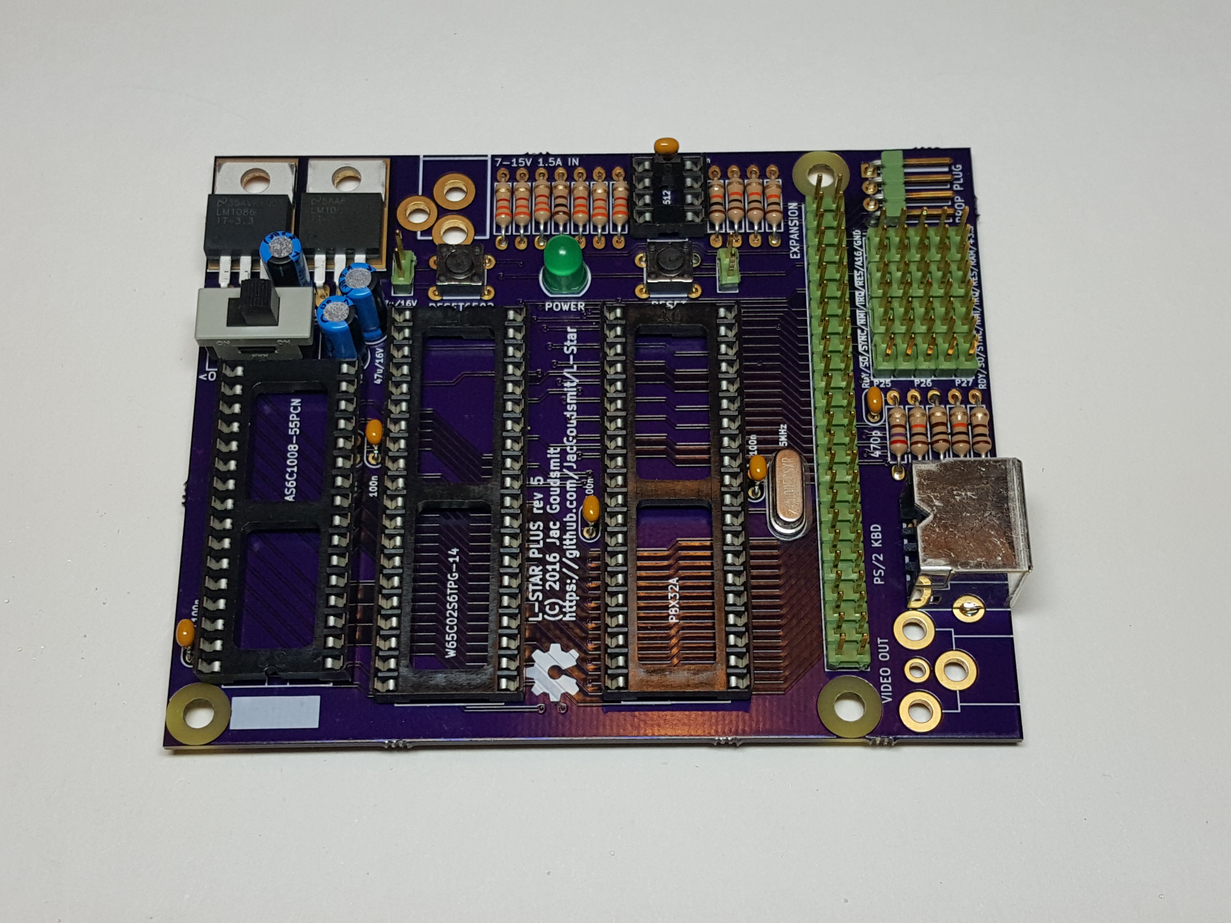
The Power Switch, and the Final Connectors
The power switch is easy. The direction doesn’t matter. Once you’ve mounted it, slide it to the right for now; that’s the “off” position.
The RCA connector is also easy, it will hold itself in place while you solder it. Don’t be stingy with the solder tin; on this connector it not only has a role as an electrical conductor but it’s also used to transfer pulling and pushing forces to the circuit board. If you don’t put enough tin, chances are that one day, you’ll plug in or unplug something and the entire connector comes off the board. If your soldering iron has temperature control, you may want to turn it up a little for this to get nice evenly solidified joints.

The holes for the power socket are unfortunately a little too big (let’s just say the data sheet is not very accurate on how big they should be), so aligning it before you solder it is a bit of a pain. So here too: solder one pin first, check the alignment (and re-solder the single pin if necessary), and once it’s perfect, solder the other pins.
Done Soldering!
Now that you’re done soldering parts onto the board, the only thing left to do is to put the IC’s in the sockets. As you can see in the picture, the pins are usually bent outwards a little when they come from the factory.
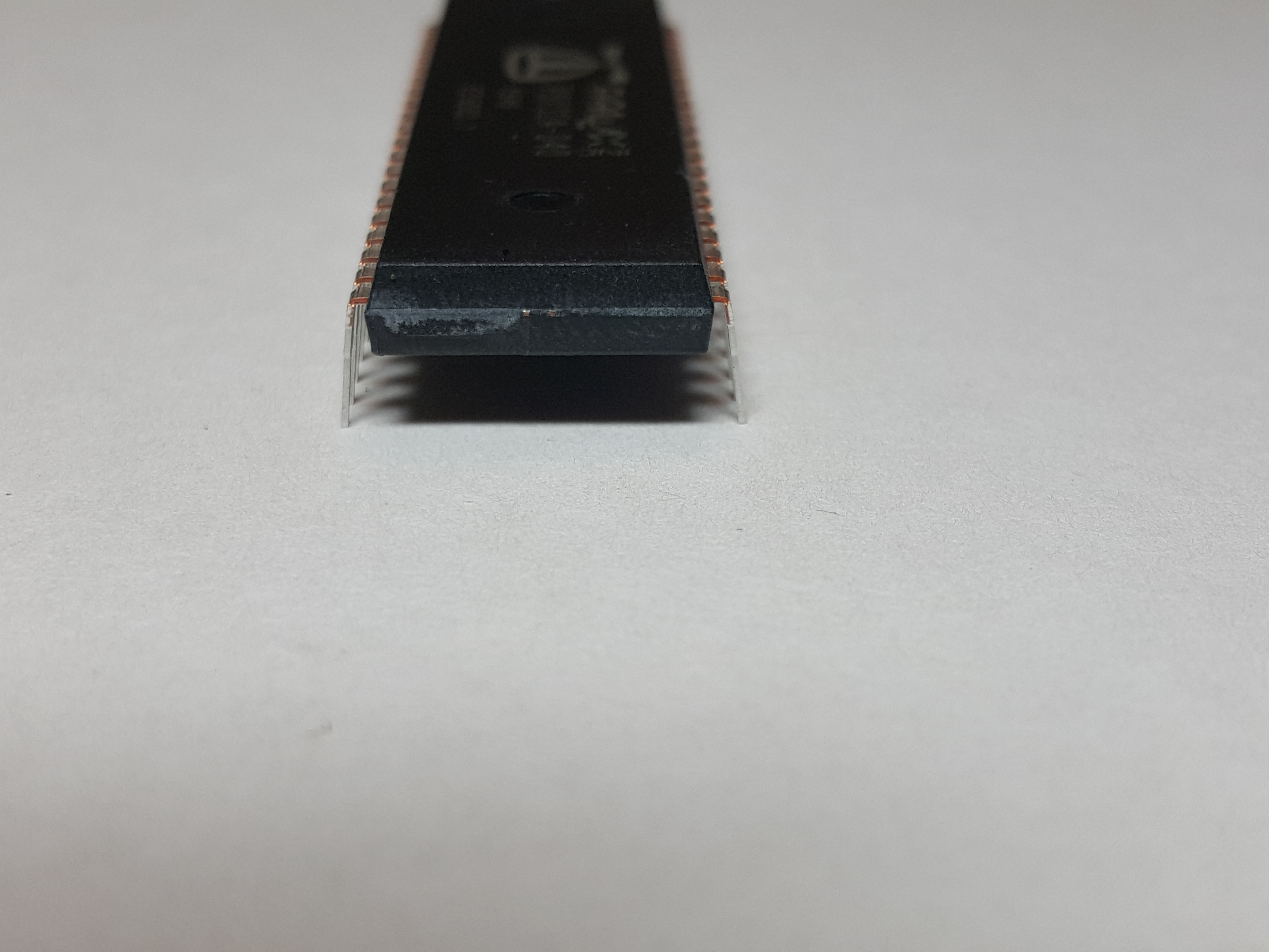
The IC’s won’t fit in the sockets correctly with the pins bent like that. The easiest way to fix this, is to carefully hold the IC sideways on both ends with two hands, and gently press it down on your work surface to bend all the pins inward just a little bit. You can also do this in the socket if you have a knack for it, but try to avoid touching the pins either way, so you don’t cause any problems with ESD.
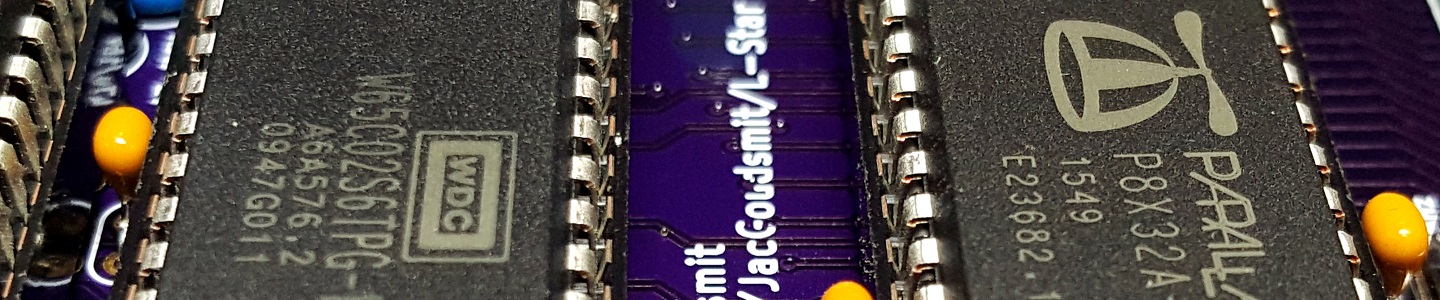
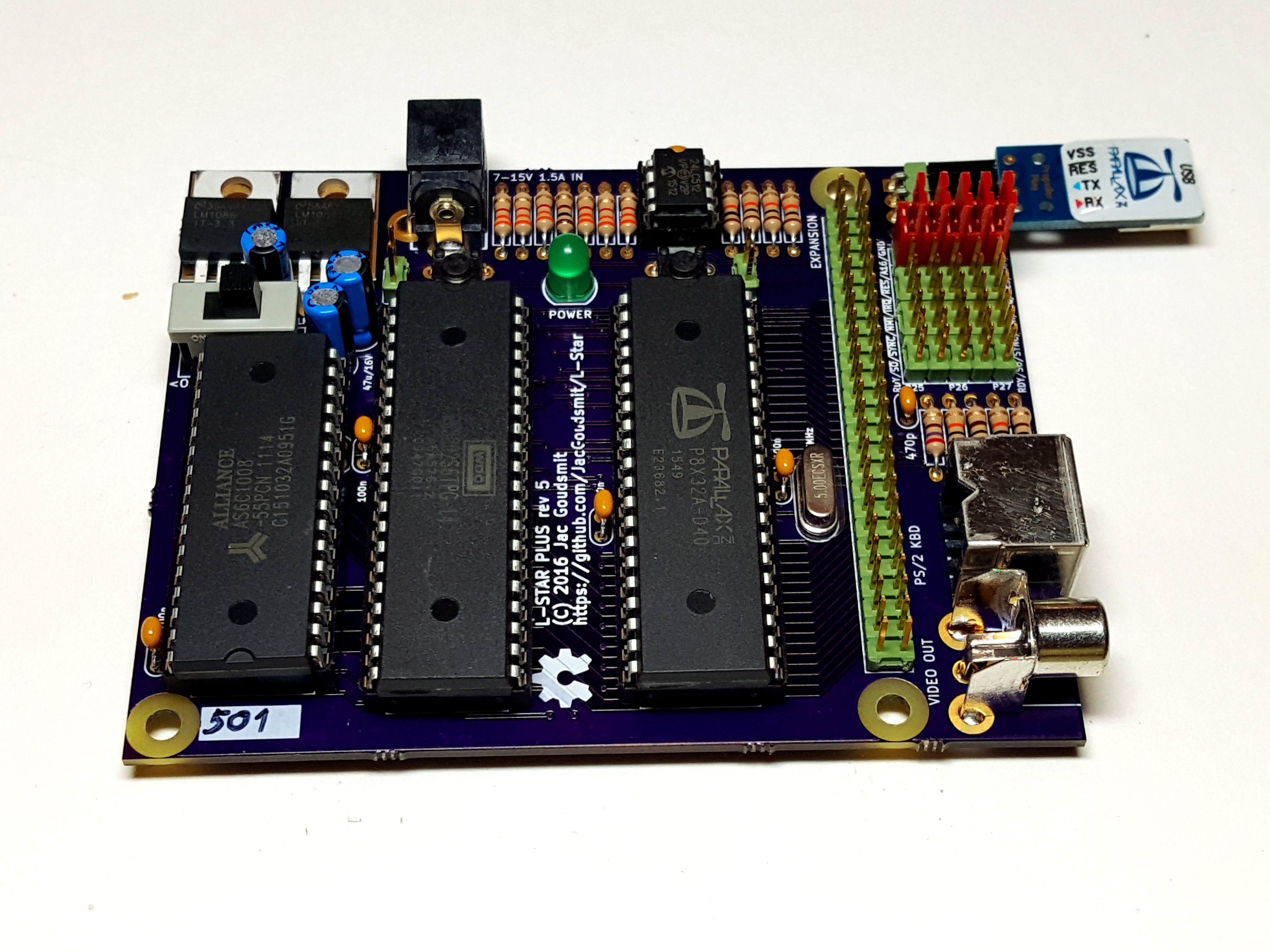
Pay attention to the markings on the chip; the Propeller and the 65C02 have the same amount of pins but if you swap them, the project will definitely not work, and you may fry them by doing that, too. The Parallax Propeller goes on the right (close to the crystal) and the WDC 65C02 goes on the left, near the memory chip.
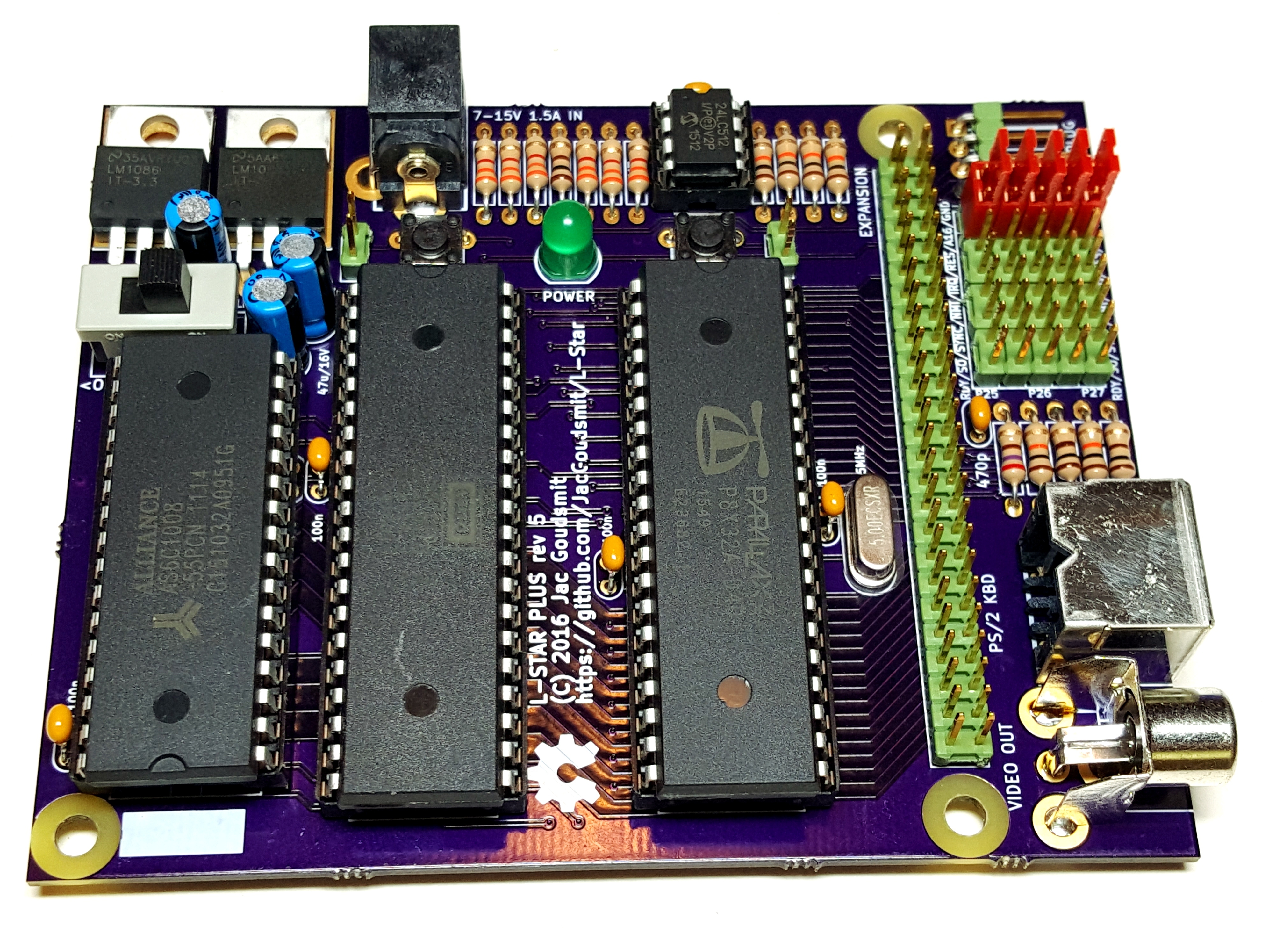
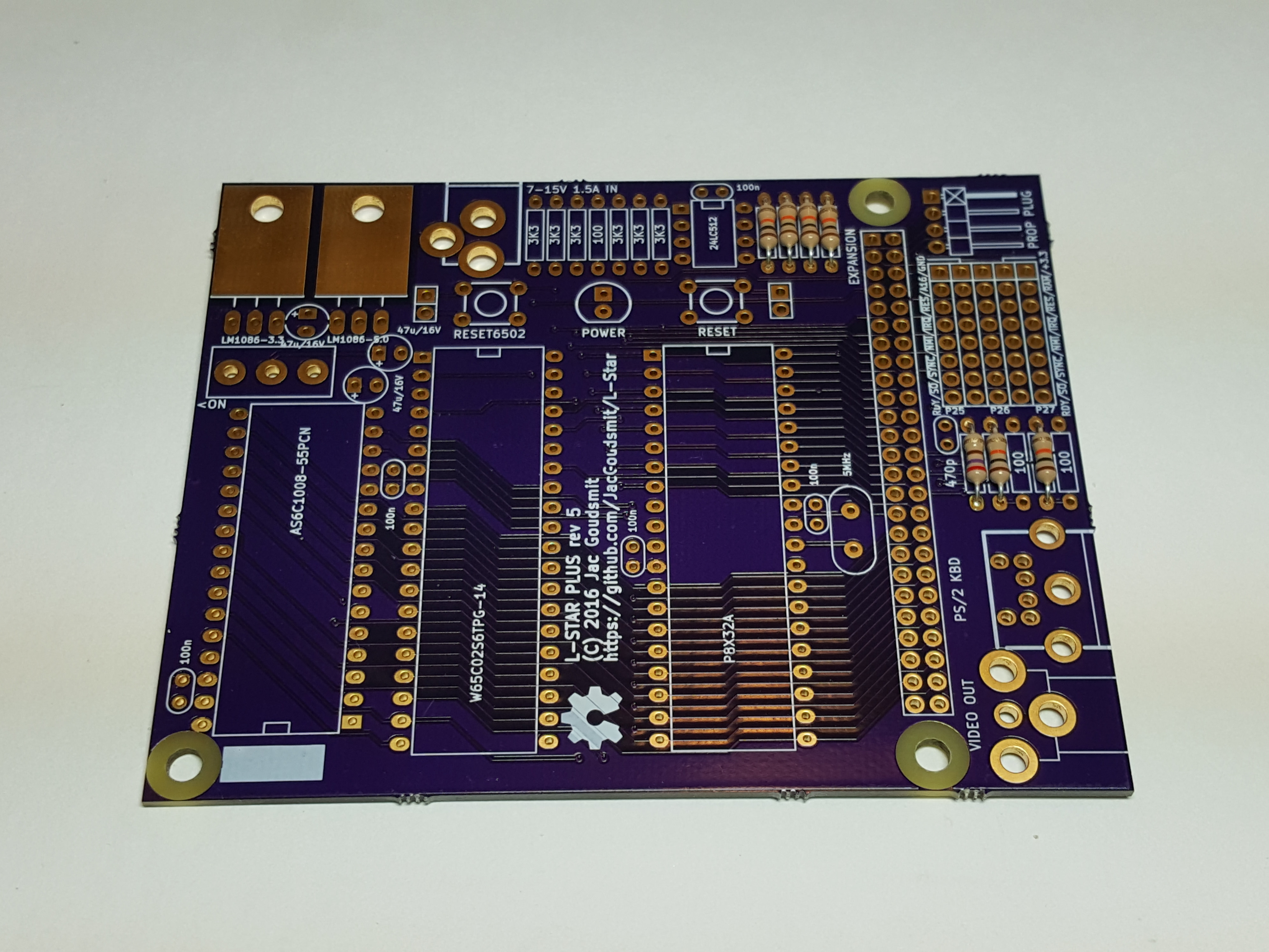
The photo at the top of this post shows where each IC goes. Pay attention to the direction: just like the sockets, all IC’s have a notch that shows where pin 1 is, and all ICs except the Alliance AS6C1008 SRAM chip on the left side have their notch pointing to the top of the board.
Shunts and Propeller Plug
You should have 5 shunts to configure how Propeller pins P25, P26 and P27 are connected. More information about this will appear elsewhere on the website, but for now, just plug them in to connect the top 2 pins of each of the 5 columns on the jumper block. This is the default configuration.
Downloading the firmware to the L-Star will also be described in other articles, but here’s one more picture showing how to connect the Propeller Plug (short: Prop Plug). The sticker side goes up (don’t plug it into the connector the other way, you might break something). For some projects, Prop Plug is the only way that L-Star can communicate to the outside world, so you have to leave it connected. For other projects, you can connect a monochrome video monitor and a PS/2 keyboard and disconnect the Prop Plug. It depends on the project.
And that concludes this tutoral. Thanks for watching, and I hope you will have lots of fun with your kit. If you have any questions, please contact me.